A few weeks ago, my coworker Blake approached me with the idea of building a weather visualizer inspired by the beautiful Rocky Mountains. The idea was to make an indoor visual display that would imitate the look and feel of the current weather outside.
Blake had a strong idea of how the project should look. He stained reclaimed wood different colors to build a mountain scene based on the view from our office. Then he handed it off to me to add the electronics and write the program. The sky was the main area where the weather would be displayed, so I added two addressable LED strips— one under a lip at the top facing downward, and one hidden behind the back mountain range facing upward. These two strips project light onto the sky area, causing a different visual effect with each animation. I also added an LED strip behind each of the lower mountains to add a small amount of ambient light, which will help define the mountains in low light.
![alt text]()
Then I worked on designing LED animations for several weather patterns: sunrise, sunset, rain, snow and clear skies. I built each of these based on images I found online of the Rocky Mountain sky during different local weather patterns.
In order to trigger the animations according to weather events, I used the Weather Underground service for IFTTT to pull and publish local weather data to my Particle Photon. I wrote a program to my Photon that will call the LED animations whenever IFTTT publishes a new weather event.
![alt text]()
If you are interested in making a version for yourself, feel free to grab my code here:
//IoT LED Weather Visualizer by Melissa Felderman for SparkFun Electronics
// This #include statement was automatically added by the Particle IDE.

#include "Particle.h"
#include "neopixel.h"

SYSTEM_MODE(AUTOMATIC);

// IMPORTANT: Set LED pixel COUNT, PIN and TYPE
#define PIXEL_PIN D2
#define PIXEL_COUNT 210
#define PIXEL_TYPE WS2812B

//setup LED strip
Adafruit_NeoPixel topStrip(PIXEL_COUNT, PIXEL_PIN, PIXEL_TYPE);

//array for even pizels for animation
int evenPixels[] = {0, 2, 4, 6, 8, 10, 12, 14, 16, 18, 20, 22, 24, 26, 28, 30, 32, 34, 36, 38, 40, 42, 44, 46, 48, 50};

void setup() {

  //initialize LED strip
  topStrip.begin();
  topStrip.show();

  //set up functions, sun for seun events, conditions for changes in weather conditions
  Particle.function("sun", sun);
  Particle.function("conditions", conditions);


}

void loop() {


}

//sun function
int sun (String value) {

  //variables for animations
  int firstStripEnd = 48;
  int secondStripStart = 49;
  int secondStripEnd = 107;
  int thirdStripStart = 108;
  int thirdStripEnd = 158;
  int fourthStipStart = 159;
  int fourthStripEnd = 210;
  int secondStripThird = 19;
  int secondStripFifth = 11;

  //sunset animation
  if (value == "sunset") {
    for ( int i = 0; i < firstStripEnd / 6 ; i++) {
      topStrip.setPixelColor(i, 30, 0, 255);
    } for (int i = firstStripEnd / 6; i < firstStripEnd / 6 * 2; i++) {
      topStrip.setPixelColor(i, 40, 0, 255);
    } for (int i = firstStripEnd / 6 * 2; i < firstStripEnd / 6 * 3; i++) {
      topStrip.setPixelColor(i, 60, 0, 255);
    } for (int i = firstStripEnd / 6 * 3; i < firstStripEnd / 6 * 4; i++) {
      topStrip.setPixelColor(i, 90, 0, 255);
    } for (int i = firstStripEnd / 6 * 4; i < firstStripEnd / 6 * 5; i++) {
      topStrip.setPixelColor(i, 120, 0, 255);
    } for (int i = firstStripEnd / 6 * 5; i < firstStripEnd; i++) {
      topStrip.setPixelColor(i, 130, 0, 255);
    }

    for (int i = secondStripStart; i < secondStripStart + secondStripFifth; i++) {
      topStrip.setPixelColor(i, 200, 50, 75);
    }

    for (int i = secondStripEnd - secondStripFifth; i < secondStripEnd; i++) {
      topStrip.setPixelColor(i, 200, 50, 75);
    }

    for (int i = secondStripStart + secondStripFifth; i < secondStripFifth * 2 + secondStripStart; i++) {
      topStrip.setPixelColor(i, 255, 100, 0);
    } for (int i = 86; i < 97; i++) {
      topStrip.setPixelColor(i, 255, 100, 0);


    } for (int i = secondStripFifth * 2 + secondStripStart; i < secondStripFifth * 2 + secondStripStart + 14; i++) {
      topStrip.setPixelColor(i, 250, 250, 50);
    }
    for (int i = secondStripStart + 22; i < secondStripStart + 26; i++) {
      topStrip.setPixelColor(i, 255, 150, 0);
    }

    for (int i = 83; i < 87; i++) {
      topStrip.setPixelColor(i, 255, 150, 0);
    }


    for (int i = thirdStripStart; i < fourthStripEnd; i++) {
      int bright = 10;
      topStrip.setPixelColor(i, bright + 17, bright + 10, bright);
    }
    topStrip.show();
    delay(100000);

  }
  //sunrise animation
  if (value == "sunrise") {
    for (int i = firstStripEnd / 3; i < firstStripEnd / 3 * 2; i++) {
      topStrip.setPixelColor(i, 90, 90, 100);
    } for (int i = 0; i < firstStripEnd / 3; i++) {
      topStrip.setPixelColor(i, 140, 140, 150);
    } for (int i = firstStripEnd / 3 * 2; i < firstStripEnd; i++) {
      topStrip.setPixelColor(i, 140, 140, 150);
    }


    for (int i = secondStripStart + secondStripThird ; i < secondStripEnd - secondStripThird; i++) {
      topStrip.setPixelColor(i, 255, 255, 100);
    } for (int i = secondStripStart; i < secondStripStart + secondStripThird; i++) {
      topStrip.setPixelColor(i, 255, 255, 25);
    } for (int i =  secondStripThird * 2 + 1 + secondStripStart; i < secondStripEnd; i++) {
      topStrip.setPixelColor(i, 255, 255, 25);

    } for (int i = secondStripStart + secondStripThird + 5; i < secondStripEnd - secondStripThird - 5; i++) {
      topStrip.setPixelColor(i, 255, 255, 150);
    }


    for (int i = thirdStripStart; i < fourthStripEnd; i++) {
      int bright = 30;
      topStrip.setPixelColor(i, bright + 20, bright + 20, bright);
    }
    topStrip.show();
    delay(100000);
  }
}

//conditions function
int conditions (String value) {

  //variables for animation
  int firstStripEnd = 48;
  int secondStripStart = 49;
  int secondStripEnd = 107;
  int thirdStripStart = 108;
  int thirdStripEnd = 158;
  int fourthStipStart = 159;
  int fourthStripEnd = 210;
  int secondStripThird = 19;
  int secondStripFifth = 11;

  //rain animation
  if (value == "rain") {
    for (int i = 1; i < 49; i++) {
      int bright = random(50, 70);
      topStrip.setPixelColor(i, bright, bright, bright);

    }
    for (int i = 50; i < 107; i++) {
      int bright = 20;
      topStrip.setPixelColor(i, bright, bright, bright);

    }
    topStrip.show();


    int rainDrop = evenPixels[random(0, 26)];

    topStrip.setPixelColor(rainDrop, 100, 100, 120);
    topStrip.show();
    delay(500);
    topStrip.setPixelColor(rainDrop, 0, 0, 0);
    topStrip.show();


    for (int i = thirdStripStart; i < fourthStripEnd; i++) {
      int bright = 10;
      topStrip.setPixelColor(i, bright + 10, bright + 10, bright);
    }

  }
  //snow animation
  if (value == "snow") {
    for (int i = 1; i < secondStripEnd; i = i + 2) {
      int bright = random(150, 250);
      topStrip.setPixelColor(i, bright, bright, bright);

    }
    for (int i = 0; i < secondStripEnd; i = i + 2) {
      int bright = random(50, 100);
      topStrip.setPixelColor(i, bright, bright, bright);

    } for (int i = thirdStripStart + 1; i < fourthStripEnd; i = i + 2) {
      int bright = random(150, 230);
      topStrip.setPixelColor(i, bright - 20, bright, 255);

    }
    for (int i = thirdStripStart; i < fourthStripEnd; i = i + 2) {
      int bright = random(50, 100);
      topStrip.setPixelColor(i, bright - 20, bright, 255);

    }

    topStrip.show();


    delay(100);

  }
  //clear animation
  if (value == "clear") {
    for (int i = PIXEL_COUNT / 3; i < PIXEL_COUNT / 3 * 2; i++) {
      topStrip.setPixelColor(i, 200, 200, 255);
    } for (int i = 0; i < PIXEL_COUNT / 3; i++) {
      topStrip.setPixelColor(i, 150, 150, 255);
    } for (int i = PIXEL_COUNT / 3 * 2; i < PIXEL_COUNT; i++) {
      topStrip.setPixelColor(i, 150, 150, 255);
    }
    for ( int i = secondStripStart; i < secondStripEnd; i++) {
      topStrip.setPixelColor(i, 200, 200, 200);
    }
    for (int i = thirdStripStart; i < fourthStripEnd; i++) {
      int bright = 10;
      topStrip.setPixelColor(i, bright, bright, bright);
    }
    topStrip.show();

  }
  //cloudy animation
  if (value == "clouds") {

    for (int i = 0; i < secondStripEnd; i++) {
      topStrip.setPixelColor(i, 30, 30, 30);
    } for (int i = thirdStripStart; i < fourthStripEnd; i++) {
      topStrip.setPixelColor(i, 10, 10, 10);
    }

  }
}
Please note: This is certainly not the most efficient or elegant program for addressing LEDs, but it works beautifully for these purposes. Please feel free to share how you would address the LEDs in the comments below.
You will need the following supplies to build the electronic component of this project:
In stock
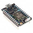
WRL-13774
Particle's IoT (Internet of Things) hardware development board, the Photon, provides everything you need to build a connected…
24In stock
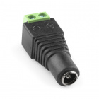
PRT-10288
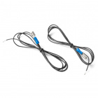
This adapter allows you to connect a barrel jack connector to bare wires. One end has screw terminals and the other has a 5.5…
28 available
COM-12026
These are bare addressable 5 meter long 5V RGB LED strips that come packed with 60 WS2812s per meter. As these are bare LED s…
In stock
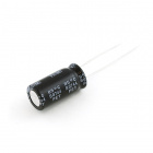
COM-08982
Electrolytic decoupling capacitors 1000uF/25V. These capacitors are great transient/surge suppressors and work well in high-v…
1In stock
DEV-13598
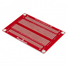
You can't have any development board without some sort of prototyping area, the SparkFun Photon ProtoShield takes care of thi…
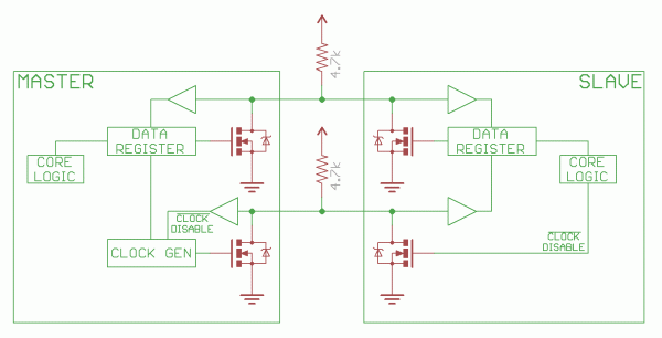
2The circuit is super simple and is illustrated in the diagram below.
![alt text]()
Having a hard time seeing the circuit? Click on the wiring diagram for a closer look.
The applet recipe is simple on IFTTT. For ‘this’ select the Weather Underground service and then the weather event that you would like your display to react to. For ‘that’ select the Particle ‘Call Funtion’ service. Select your Photon and function name in the first field, and then add the value that you would like to pass through in the second.
![alt text]()
Share your thoughts and favorite weather projects on Facebook, Twitter and in the comments below!
comments | comment feed